current location : home

Unleashing Power and Efficiency The 800kW Scroll Air-Cooled Chiller Redefines Industrial Cooling

In the world of industrial cooling, scroll air-cooled chillers are spearheading an energy-efficiency revolution. Among them, the newly launched 800kW chiller by H.Stars Group has quickly become a topic of industry discussion. But what qualifies as a “large-scale” unit in this field? Let’s decode the standards of industrial chiller classification from a technical perspective.

industrial refrigeration solutions 800kW air cooled chiller


1. Understanding Chiller Size Classifications

In the HVAC industry, the size of a chiller is defined by more than just its physical footprint. According to ASHRAE (American Society of Heating, Refrigerating and Air-Conditioning Engineers), scroll air-cooled chillers can be categorized by cooling capacity as follows (for reference):
• Small Units: <200kW
• Medium Units: 200–500kW
• Large Units: >500kW
This classification considers system integration, efficiency curves, and actual application environments—not just output power.
International giants like Trane and Carrier follow similar sizing logic. 500kW often marks the dividing line between commercial and industrial systems. Units above this threshold typically feature multiple compressors, subcooling technology, and advanced industrial-grade designs—with COP (Coefficient of Performance) values exceeding 3.8 and meeting China's GB19577-2015 first-level energy efficiency standard.

2. Where Does the 800kW Unit Stand?

H.Stars’ 800kW scroll chiller features a dual-rotor variable frequency compressor system and sits firmly in the upper tier of industrial cooling. Compared to conventional 500kW models, it reduces metal consumption per kilowatt of cooling by 18% and boosts its IPLV (Integrated Part Load Value) to 4.2. This translates to an annual power saving of approximately 120,000 kWh based on 3,000 operating hours per year.
In field testing at a cold chain logistics center, the unit maintained full-capacity operation even in harsh 45°C ambient conditions—demonstrating excellent environmental adaptability.

3. Compact Design Meets High Power

Compared with McQuay’s MWC 650kW chiller (5.2m² footprint), the H.Stars 800kW unit achieves higher capacity while maintaining a smaller footprint (4.8m²). This compact modular design simplifies transportation and installation.
Its smart multi-unit control system supports parallel operation of up to 8 units, enabling a combined capacity of up to 6400kW. This makes it a perfect fit for large-scale data centers, chemical processing plants, and industrial manufacturing facilities.


energy-efficient chillers modular chiller system


4. Market Trends: Big Units, Bigger Opportunities

With the rise of China’s “New Infrastructure” initiative, demand for high-capacity chillers is surging. As of 2022, chillers over 500kW now account for 38% of the market—up from just 23% five years ago.
These systems are essential in semiconductor fabs and battery manufacturing lines. For instance, after a major lithium battery producer adopted the H.Stars 800kW chiller, their cooling energy consumption dropped by 31%, while product yield increased by 2.7%.

5. Smart Cooling for Industry 4.0

To meet the demands of intelligent manufacturing, H.Stars integrates IoT-based remote monitoring into its chillers. Each unit tracks 132 real-time operational parameters. Combined with machine learning algorithms, the system optimizes energy use dynamically, transforming the 800kW chiller from a mere cooling unit into a critical node in the industrial IoT ecosystem.
As Industry 4.0 accelerates, the emergence of H.Stars’ 800kW scroll chiller redefines what a large-scale cooling solution looks like. It's more than a machine—it's a symbol of China’s rising capability in precision industrial refrigeration, and a gateway to a smarter, more efficient future.
When cooling capacity crosses new thresholds, what follows is not just power—but an entire shift in the energy efficiency paradigm.


...

The use of moisture permeability tester

The moisture permeability tester is a professional device used to measure the water vapor transmission rate (WVTR) of textiles, films, non-woven fabrics and other materials. The following are the standard operating procedures and technical points.


I. Equipment structure and principle

Core components

1. Test chamber: sealed chamber with controllable temperature and humidity (usually divided into dry/wet chamber)

2. Weighing system: high-precision balance (0.001g resolution)

3. Temperature control system: PID precise temperature control (range 20-50℃±0.5℃)

4. Humidity system: saturated salt solution or steam generator

5. Data acquisition: automatic recording of mass changes and temperature and humidity


Test principle

Positive cup method (ISO 2528): water vapor permeation from wet chamber to dry chamber

Inverted cup method (ASTM E96): water vapor absorption from dry chamber to wet chamber

Dynamic method (JIS L1099): determination of water vapor carried by airflow


II. Standard operating procedures

1. Sample preparation

Cut a circular sample with a diameter of ≥70mm (no creases/breaks)

If testing multiple layers of materials, stack them according to the actual use direction

Pretreatment: equilibrate at the test temperature and humidity for 24h (GB/T 12704 requirements)


2. Equipment initialization

1. Turn on the constant temperature water bath (set to 23℃ or 38℃)

2. Prepare saturated salt solution:

Dry environment: Mg(NO₃)₂ (RH≈53%)

High humidity environment: K₂SO₄ (RH≈97%)

3. Calibrate the balance (use standard weights)

3. Sample loading and sealing

1. Fix the sample at the mouth of the test cup:

- Positive cup method: add distilled water (liquid surface 3mm away from the sample)

- Inverted cup method: add desiccant (anhydrous CaCl₂)

2. Press with silicone seal to ensure no side leakage

3. Weigh the initial mass (m₀) to an accuracy of 0.001g

4. Test execution

1. Place the test cup in a constant temperature and humidity chamber

2. Set parameters:

Temperature: 23±1℃ or 38±1℃ (select according to the standard)

Air flow rate: 0.5-1.0m/s (dynamic method needs to be set)

Test interval: 1h/time (static method)

3. Start the test, the system automatically records the mass change (m₁, m₂...mₙ)

5. Data processing

Water vapor permeability meter:

WVTR = (Δm×24)/(A×t) Unit: g/(m²·d)

Δm: mass change (g)

A: effective test area (m²)

t: test time (h)

Example:

If the mass decreases by 0.12g within 24h and the test area is 0.00283m², then:

WVTR = (0.12×24)/0.00283 = 1017.7 g/(m²·d)


Email: hello@utstesters.com

Direct: + 86 152 6060 5085

Tel: +86-596-7686689

Web: www.utstesters.com

...

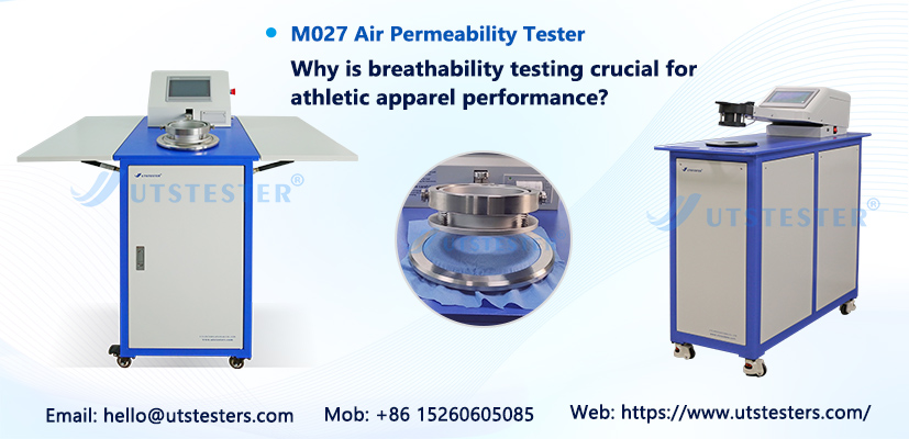
Uses of fabric air permeability tester

The fabric air permeability tester is an instrument specially used to measure the air permeability of fabrics (such as clothing, footwear, industrial textiles, etc.). Its core purpose is to evaluate the ability of materials to allow air to pass under different pressure difference conditions. The following are its main application scenarios and purposes:


1. Quality control and production optimization

Production process verification: Ensure that the air permeability of fabrics during the production process (such as textile, coating, lamination, etc.) meets the design standards to avoid performance degradation due to process deviations.

Batch consistency detection: Compare different batches of raw materials or finished products to maintain the stability of product air permeability.


2. Functional clothing and equipment development

Sports/outdoor clothing: Test the air permeability of products such as assault jackets and mountaineering clothes, and balance the needs of windproof and moisture removal (such as the research and development of fabrics such as GORE-TEX).

Protective equipment: Evaluate the air permeability of medical protective clothing and industrial dustproof clothing to ensure the protective effect while avoiding stuffiness.

Shoe materials and tents: Optimize the air permeability of upper materials or tent fabrics to improve wearing comfort or ventilation performance.


3. Industry standards and certification

Compliance testing: meet international standards (such as ISO 9237, ASTM D737, GB/T 5453, etc.) and obtain product certification (such as CE, OEKO-TEX).

R&D benchmarking: compare competitor or industry benchmark data to guide new product development.


4. Material research and innovation

Evaluation of new materials: test the air permeability efficiency of innovative materials such as nanofibers and breathable membranes to promote technology applications.

Analysis of multi-layer composite materials: study the impact of different laminate structures (such as non-woven fabrics + films) on overall air permeability.


5. User experience and market competitiveness

Comfort quantification: convert air permeability data (such as mm/s or cfm) into product selling points (such as "air permeability increased by 20%)" to enhance market persuasiveness.

Problem diagnosis: for the "stuffy" problem complained by users, locate material or design defects through testing.


Brief description of test principle

The instrument applies a controllable air pressure difference on both sides of a fixed area of fabric to measure the volume of air (or flow rate) passing through per unit time. The results are usually expressed as air permeability (such as L/m²/s) or air permeability resistance, with higher values indicating greater air permeability.


Key parameters for selecting a tester

Test standard compatibility (such as support for multiple international standards)

Range and accuracy (adapting to different materials from dense down-proof fabrics to sparse mesh fabrics)

Automation functions (such as digital pressure regulation, direct data export)


This type of instrument is indispensable in textile laboratories, quality inspection agencies and R&D centers, and directly affects the functional positioning and market acceptance of products.

Email: hello@utstesters.com

Direct: + 86 152 6060 5085

Tel: +86-596-7686689

Web: www.utstesters.com

...

Will high temperature of stepper motor cause step loss

High temperature environment can affect the efficiency and accuracy of stepper motors, which may lead to step loss.

1、 Working principle of stepper motor

A stepper motor is a type of motor that converts electrical pulse signals into rotational angle outputs. Each time a pulse signal is received, the stepper motor rotates a fixed angle, usually 1.8 or 0.9 degrees. Therefore, stepper motors can accurately control the rotation angle and speed, and are often used in mechanical equipment that requires precise control.

2、 The impact of high temperature environment on stepper motors

High temperature environments can have a negative impact on the operation of stepper motors. Firstly, high temperatures can cause the temperature of the coils inside the motor to rise, thereby increasing resistance and affecting motor performance. Secondly, the aerodynamic performance in high-temperature environments is poor, which can reduce the cooling efficiency of the motor. Finally, high temperature may also cause expansion and deformation of motor materials, intensify friction, and affect the accuracy and efficiency of the motor.

3、 Step loss problem of stepper motor in high temperature environment

In high temperature environments, the problem of step loss in stepper motors is quite serious. When the temperature of the motor increases, the resistance of the coil will increase, which will cause a decrease in current and affect the rotation of the motor. In addition, high temperature environments can weaken the cooling efficiency of the motor, further exacerbating the problem of step loss. Therefore, to ensure the stability and accuracy of the stepper motor, special protection and control are required in high-temperature environments.

4、 How to solve the problem of step loss in stepper motors under high temperature environment

To solve the problem of step loss of stepper motors in high temperature environments, we can start from the following aspects:

1. Use high temperature resistant materials: Choosing high temperature resistant materials can reduce the high temperature impact on the motor.

2. Regular motor inspection: Regularly check the temperature and condition of the motor to promptly identify and solve problems.

3. Strengthen cooling measures: Increase cooling measures for the motor, such as adding heat sinks, installing fans, and reducing motor workload.

4. Use temperature sensors: Install temperature sensors to monitor the motor temperature in a timely manner, and issue alarms and handle issues promptly when the temperature is too high.

High temperature environment can have a certain degree of impact on the efficiency and accuracy of stepper motors, and even cause step loss problems. To ensure the stability and accuracy of the stepper motor, it is best to use high temperature resistant stepper motor

Ctrl-Motor is the overseas business office established in Shenzhen by DDON (Chengdu, headquartered in Sichuan, China. The company has a team of nearly 100 senior engineers, specializing in the production of special motors ranging from deep low temperature of - 196°C to ultra - high temperature of +300°C and extreme environments.


...

Technical Characteristics and Engineering Applications of Rapid Temperature Change Test Chambers

This article analyzes the system architecture and technical characteristics of rapid temperature change test chambers, by systematically studying the technical parameters and functional design of key components, it provides theoretical guidance for equipment selection and process optimization.


1.Technical Principles and System Architecture

Rapid temperature change test chambers operate based on thermodynamic transfer principles, achieving nonlinear temperature gradient variations through high-precision temperature control systems. Typical equipment can attain temperature change rates ≥15℃/min within a range of -70℃ to +150℃. The system comprises four core modules:

(1) Heat exchange system: Multi-stage cascade refrigeration structure

(2) Air circulation system: Adjustable vertical/horizontal airflow guidance

(3) Intelligent control system: Multivariable PID algorithm

(4) Safety protection system: Triple interlock protection mechanism


2.Analysis of Key Technical Features

2.1 Structural Design Optimization

The chamber adopts modular design with SUS304 stainless steel welding technology. A double-layer Low-E glass observation window achieves >98% thermal resistance. The CFD-optimized drainage channel design reduces steam condensation to <0.5 mL/h.


2.2 Intelligent Control System

Equipped with Japan-made YUDEN UMC1200 controller.


2.3 Refrigeration System Innovation

Incorporates French Tecumseh hermetic scroll compressors with R404A/R23 refrigerants.

 3.Safety and Reliability Design

3.1 Electrical Safety System


  • Complies with IEC 61010-1 CLASS 3
  •  
  • Schneider Electric components with full-circuit isolation
  •  
  • Grounding resistance <0.1Ω
  •  
  • Overcurrent protection response <0.1s


3.2 Multi-level Protection

  • Triple-channel PT100 temperature monitoring
  • Dual pressure switches
  • Dry-burn humidity protection
  • Emergency pressure relief valve


4.Technological Applications

(1) Aerospace: Thermal-vacuum testing for satellite components

(2) New energy vehicles: Battery pack thermal shock tests

(3) Microelectronics: Chip package reliability verification

(4) Materials science: Composite interlayer thermal stress analysis


5.Technological Trends

(1) Multi-stress coupling tests: Temperature-vibration-humidity simulation

(2) Digital twin integration: Virtual system modeling

(3) AI-driven parameter optimization: Machine learning-based curve tuning

(4) Energy efficiency: 40%+ heat recovery rate


Conclusion: With increasing reliability requirements in advanced industries, future development will emphasize intelligent operation, high precision, and multidimensional environmental simulation. Subsequent research should focus on integrating equipment with product failure mechanism models to advance environmental testing from verification to predictive analysis.

Click to view related products.

Lab Companion, your trusted brand.

...

How to Use CNC Machine Step by Step?

The automated manufacturing tool known as Computer Numerical Control (CNC) operates through programmed code instructions to shape and cut materials including metal, wood, foam and plastic. The process of learning CNC equipment setup and operation requires both study and practice yet basic CNC mastery enables both hobbyists and professionals to create precise parts efficiently.

This guide provides step-by-step education for beginners who lack CNC experience through detailed explanations of standard CNC workflow preparation and programming and machining and maintenance procedures. The article provides essential information about CNC terminology and equipment components and safety protocols which every CNC operator must learn.


What is a CNC Machine?

CNC machines operate as automated milling and routing tools with drilling and cutting capabilities which use computerized controls to transform stock materials into custom parts and designs. The automation of manual machining operations through CNC systems delivers enhanced precision and speed together with repeatability and complex capabilities beyond what human craftsmen could achieve.

The main CNC machine categories consist of milling machines, lathes, routers, laser cutters and plasma cutters. Advanced 5-axis CNC machines have the capability to execute complex three-dimensional cutting operations. The majority of CNC machines used by hobbyists function as vertical milling machines with adjustable beds or small routers.

Common Types of CNC Machines

● CNC Mill - A versatile computer controlled vertical milling machine center, typically with a movable table or bed that the workpiece is secured to. Common configurations are 3-axis (X, Y, Z motion) and 5-axis (with rotary axes) controlled.

● CNC Router - A gantry style machine that moves a spindle over a stationary table and is ideal for routing wood or soft materials. Z-axis is controlled, allowing intricate 2D and 2.5D shapes.

● CNC Lathe - Highly rigid and accurate computerized turning center that rotates the part while the cutting tools move radially to cut complex patterns on the sides of the workpiece.

● CNC Plasma Cutter - Uses a digitally controlled plasma arc to melt and cut electrically conductive materials like stainless steel or aluminum. Tolerances down to 1mm.

● CNC Laser Cutter - A CO2 laser beam burns through sheet stock by either vector cutting outlines or rastering patterns. Ideal for precise, clean cuts in wood, acrylic, fabrics, and paper.

● CNC Waterjet - An extremely high pressure stream of water with abrasives cuts through metal, glass, foams, plastics, and composites along a programmed path with zero heat damage or fumes.

Key Components and Terminology

It's vital to understand the physical components and motion capabilities of a CNC machine before attempting operation:

● Axes - The moving directions labeled X, Y, Z that the tool or part can be positioned along using coordinated motion control.

● Spindle - The electric high speed motor that rotates the cutting tool or bit at RPMs sufficient for machining.

● Collet - The clamping chuck on the machine's spindle that grips and secures the cutting tools.

● Gantry - The bridge assembly that allows movement of spindles or material over the workspace below.

● Working Envelope - The maximum part size capacity based on the machine's travels along each axis.

● Controller - The computer and monitor that converts CAM-generated G-code into electrical signals that command axis stepper motors.

● Stepper Motors - Precise digital actuators that can position the axes or spindle speed based on input pulses.


Preparation Before Using a CNC Machine 

A CNC device requires proper setup before turning on the power for any cutting operation to proceed safely. The failure to properly set up the machine and workspace creates risks that range from equipment damage to serious injuries from flying debris and sparks and other potential hazards.

Safety Precautions and Gear

You should examine both the operational manual and risk assessments for the CNC model you operate because it contains unique hazards. General safety tips include:

● Protect your eyes with safety glasses and your ears with ear protection and wear shoes that cover your entire foot while operating equipment.

● Check for machine stability before adjusting the leveling feet when operating on an uneven floor surface.

● The work area must have open pathways for access and no slippery surfaces should exist.

● Long hair should be secured and all loose clothing and jewelry and other objects must be removed to prevent them from getting trapped in machine parts.

● Keep a first aid kit and fire extinguisher easily accessible in the work area.

● The machine operator needs to install methods that reduce risks according to the machine specifications and material cutting requirements.

Understanding the Blueprint or CAD Design

CNC machining requires a digital design file generated from CAD software which defines the desired part geometry. Common file types are .DXF files or CAM specific files with toolpath information. The operator must fully understand the critical dimensions, geometries, any datum references or other specifics called out in the blueprints or models before attempting to replicate them physically.

Pay attention to fine details regarding necessary hole sizes, surface finishes, tolerances, or notes clarifying setup instructions or machining steps. Planning may be required for necessary fixture creation or workholding choices as well.

Choosing the Right Material and Tools

The raw material blanks must match the type and dimensions specified in the cutting plan. Ensure adequate stock is available for the entire job or production run with consideration for potential scrap and defects needing discarded. Stable sheet goods should be flattened if warped to allow proper holding.

Selecting suitable cutting tools is also mandatory for efficient material removal without tool failure or damage risk. Consider factors like these when tooling up:

● Flute count, helix angle, length, diameter based on optimum chip loads

● Tool coating durability for the specific material hardness and run durations

● Insert shape and angle tuned for effective shearing action

● Tool stick out constraints to minimize vibration and deflection

Sharp and undamaged tooling is essential for clean, accurate cuts and optimized machine performance.

Step-by-Step Guide to Operating a CNC Machine 

Once the necessary safety steps have been performed and the job has been programmed and tooled up for, the hands-on CNC operation can commence. The following procedural checklist summarizes the key usage steps that typical small-scale CNC workflows follow from power-on to finished parts.

Step 1: Setting Up the Machine

Locate the master electrical disconnect switch and set it to "ON" to energize the device. Then toggle the operational power button to initialize the control panel and operating system. Stepper motors will likely need to index their positions as part of this startup synchronization.

Per manufacturer guidance, certain critical machine components may require time to reach steady-state operating temperatures before cutting begins. Spindle bearings, ballscrews, and electronics need proper heat levels and lubricant viscosity to function accurately and reliably.

Step 2: Securing the Workpiece

Degrease and clean the table surface or subplate where workpieces will be mounted. Select appropriate vises, clamps, toe clamps or custom fixturing solutions to securely hold parts in place while managing chip and coolant runoff.

Improperly aligned parts risk tool strikes, dimensional errors, unwanted vibration and other technical issues. Confirm with indicators like dial test indicators that the workpiece is both immobile and precisely oriented relative to the machine zero position.

Step 3: Loading the CNC Program

.NC files contain numerical control instructions to direct machine movements and functions. Other extensions like CNC or TAP also store coded cutting data. CAM software converts 3D models to G-code toolpaths automatically.

Use USB drives, Ethernet networks or the controller interface to upload program files created offline into the CNC system's memory storage location. Verify the proper file name and storage path to avoid operational issues.

Step 4: Tool Setup and Calibration

Carefully insert cutting bits fully into the machine's collet or chuck, avoiding contact with the delicate flutes. Tighten to appropriate torque specifications with matched wrench sizes.

Input or digitize each tool's radial dimensions and tip length values to record into the tool library offset register. This allows compensation for differences during program run time.

Trial actual hole drilling, surfacing or profile cutting to dial-in and validate entries. Continually refine offset data until satisfied with tool behavior before starting final program.

Step 5: Setting Machine Zero

The CNC controller orients all commanded positioning, rapid moves and cutting passes to a defined coordinate system tied to the workpiece location and stock boundaries.

Instruct the machine to travel to touch off points helping correlate the vise or fixture coordinates to the workspace axis positions reported. This "zeroing process" syncs the programming perspective to actual tool tip placement.

Step 6: Dry Run and Simulation

Always simulation full G-code program execution at rapid speeds without engaging cutting. Seriously risk and liability reduction step to validate positioning, catch any crashes.

Many advanced CNC controllers include a realistic 3D graphical environment rendering the entire machining sequence. Use to help visualize program behavior.

Step 7: Executing the Machining Process

With a proven, vetted toolpath program now loaded, carefully begin the full production run. Monitor constantly for any alarm conditions or abnormalities requiring an immediate feed hold or full stop. No unattended operation.

Control feed rates, spindle speeds and other critical parameters must match both program settings and equipment capacities to achieve target finish quality and prevent tool breakage. A conservative approach is smart initial practice.

Step 8: Finishing the Process

Upon fully completing all encoded operations without any axis overtravel errors, the CNC machine will signal job done status. Inspect finished part inside the machine before removal.

Carefully remove workpiece from fixture or vise without damage after power disabled. Also clear tool debris and machining detritus from moving components near way covers to prevent accumulation.


Post-Processing and Quality Checks 

Deburring and Surface Finishing

Manually reviewed the machined workpiece for any remaining burrs, casting flash or undesirable surface inconsistencies needing improvement using bench grinding or sanding techniques. Edge rounding helps strengthen components against crack propagation as well.

Dimensional Inspection and Tolerances

Confirm all critical to function dimensions and 3D geometries match engineering requirements and product specifications before proceeding to secondary operations or customer delivery. Record data trends.

Common Errors and Troubleshooting

Pay close attention to these known CNC machining fault modes when inspecting finished pieces for accuracy:

● Chatter marks - Insufficient rigidity during cutting passes

● Tapered walls - Improperly trammed or aligned machine axes

● Steps in floors - Dull cutters with reduced chip loads

● Overcut radii - Excessive tool stick out and deflection

Thoughtfully tune operating parameters and mechanical adjustments until achieving satisfactory tolerance and surface finish capability. Eliminate the root cause - don’t just treat one-off symptoms.

Maintenance Tips for CNC Machines

Consistently performing scheduled preventative maintenance extends the productivity and lifespan of CNC equipment. Follow the OEM recommendations for cleaning methods, lubricants, and component replacement intervals.

Daily, Weekly and Monthly Checklists

● Blow off metal chips and debris near moving components using compressed air after operations

● Vacuum coolant tanks and chip conveyors to avoid clogging sensitive pumps and tooling

● Check machine structure bolts for any loosening due to vibration

● Lubricate linear rails, ballscrews and gear cases per guidance

● Inspect machine wiring for rodent or moisture damage

Tool Wear and Replacement

Replace or resharpen cutting bits immediately once tolerances start to suffer or finish quality degrades. Worn tools increase heat and forces, accelerating component fatigue. Proactively managing tooling condition prevents damage cascades.

Software and Firmware Updates

Import updated G-code postprocessors, machine interfaces and motor control firmware from vendors when available to fix bugs and unlock new capabilities. However, carefully test any revisions adequately before relying upon for production.


CNC Programming Basics (Optional for Beginners)

While generating optimized toolpaths from CAD files involves specialty CAM software expertise, beginners can start learning fundamentals with these concepts:

Intro to G-Code and M-Code

These instruction sets use alphanumeric formats to control axes motion, spindle actions, coolant states and other CNC functions. Mastering code structures helps operators program manually or troubleshoot files.

CAM Software Overview

Powerful interface programs like Fusion 360, MasterCAM and SolidWorks translate 3D models into machining operations, accounting for fixtures, tools and stock. The output is simulatable G-code.

Editing and Optimizing CNC Code

Understanding how to modify speeds, feeds, tool selections within code files allows refining cycle times, quality factors and tool loads. But changes can also introduce new problems if unfamiliar with underlying calculations.


Conclusion

Learning to safely and efficiently operate CNC machining centers requires studying key concepts like coordinate systems and G-code programming before attempting cutting. Additionally, properly preparing raw materials, creating fixtures, and selecting suitable cutting tools are all vital for success.

Carefully stepping through important procedures like defining machine zero, mounting workpieces, loading programs, and calibrating offsets will build core competencies over time. Gradually implement speeds and feed rates that optimize cycle times without compromising finish quality or accuracy.

Consistently maintaining CNC equipment and inspecting parts for errors allows continually dialing in tolerances and surface finishes towards optimum performance. Mastering these fundamental principles of CNC usage is challenging but very rewarding.

...

CNC Router vs Milling Machine A Comprehensive Comparison

CNC (computer numerical control) has changed the face of the manufacturing industry by automating the motion of factory tools and machinery using pre-programmed software. It has changed the process of how components are manufactured where all the three-dimensional cutting jobs can be done with the help of a single set of prompts. CNC routers and CNC milling machines are two of the more popular types of CNC machinery that manufacturers can consider for their workshop or manufacturing facility.

To assist your decision on that matter, this article compares the characteristics, applications, and suitability of CNC routers vs milling machines. This comparison will serve as your comprehensive guide to understand the nuances of each tool, whether you are a hobbyist seeking to optimize your workshop or a business owner aiming to strengthen production capabilities.


What is a CNC Router?

Generally, a CNC router is a computer-controlled cutting machine that is primarily used for softer applications. It acts like a normal hand held router, but with the added advantage of being able to computer control it, which minimizes the possibilities of cutting errors by small percentages. These machines are powerful tools that can slice, engrave, carve, and shape different materials with great efficiency and precision.

Key Features

Common characteristics of CNC routers are:

● High-RPM Spindles: CNC routers don't simply run higher RPMs than milling machines, they run much faster feed rates as well, meaning less time will be spent cutting. With a high-speed operation, they're well suited for softer materials.

● Gantry Style: Most CNC routers fall under the gantry-style design, where the cutting head moves over a stationary workpiece. Having two vertical columns on each side with the cutting tool spanning a horizontal frame, this design is perfect for working on large sheets of material.

● Multi-Dimensional Axis: CNC routers usually can move in 3 to 6 axes. Standard 3-axis machines can cut up and down (Z-axis) as well as in the X and Y direction, while more advanced 4-axis and 5-axis models can cut rotationally, coming in from other angles to create more intricate designs.

● Larger Work Area: In general, CNC routers have a larger cutting space, making them very convenient for working with sheet materials as well as for large format objects.

● Material Compatibility: CNC routers are typically designed for softer materials like wood, plastics, foam, composites, and softer metals such as aluminum and magnesium.


What is a CNC Milling Machine?

CNC milling machines are heavy-duty, computer-operated cutting tools for machining harder materials with high precision. Unlike routers, which prioritize cost and speed, milling machines are designed for strength and rigidity and can handle heavier cutting operations with impressive precision.

Key Features

Features of a CNC milling machine:

● Rigidity: CNC mills are built with a heavy-duty, permanent frame that allows them to perform highly vertical and horizontal cutting. This inflexible construction enables them to process more resilient materials while ensuring the utmost precision.

● Low-Speed High-Torque Spindle: A CNC mill uses a spinning spindle like a router except that it only spins between 1,000 to 20,000 RPM compared to a router. These industrialist titanium cuts give them the ability to make shallower cuts in harder things, but without sacrificing accuracy

● Multiple Axes: Basic CNC mills work on 3 axes while more advanced models can have up to 12 axes of movement. Such a wide range of motion allows complex machining that is impossible with simpler equipment.

● Precision: CNC mills are only the same CNC machines that can be designed with precision and dimensional accuracy in mind, making design projects with tight tolerances and intricate designs perfect for doing.

● Material Compatibility: CNC milling machines can cut harder materials, they are perfect for cutting metals (steel, titanium, stainless), plastics, and composites. They could offer the services to cut these materials at a high speed all without losing precision and accuracy.

Key Differences Between CNC Router and Milling Machine

Design and Structure

CNC routers are generally built in lightweight, gantry configurations, with the cutting head moving over a stationary workpiece. This involves two vertical columns on either side of the cutting tool, which moves along a horizontal framework. It is less rigid than a milling machine and thus has considerably lower precision capabilities, however is much faster and has a much larger area of operation.

CNC milling machines are designed with a robust, cast iron or steel framework that ensures exceptional rigidity and stability when in operation. They have a fixed frame and a movable workpiece for vertical and horizontal cutting.

Material Compatibility

CNC routers are made to cut softer materials. They shine at cutting wood, plastics, foam, composites, and soft metals — aluminum and magnesium. They can also work quickly, which is ideal for processing these materials without excessive heat or damage.

Due to this fact, CNC milling machines are designed to work with much hard and inflexible materials. They are able to process steel, stainless steel, titanium, copper, and other solid metals that would harm or damage a CNC router. Different sorts of metals like aluminum and steel are too hard for regular routers to do a good job because they will go deep while CNC routers won't.

Precision and Accuracy

The CNC router has a relatively good precision that is sufficient for many applications (it is usually not comparable to a milling machine). They have a less rigid construction and higher operating speeds that result in increased vibration and a propensity for deflection during cutting operations.

They offer much higher precision and accuracy compared to CNC milling, which makes them great for complex geometries and intricate designs. Their inflexible construction minimizes vibration and tool deflection, making for extremely precise cuts within tight tolerances. CNC mills use more advanced control systems that allow the cutters to move very precisely over rigid structures.

Speed and Torque

CNC routers run at much higher RPM than milling machines (18,000–24,000+ RPM). During high-speed operations, feed rates are high and material removal is rapid within soft material. ​However, the rotary cutters of CNC routers provide less torque, making them less effective for deep cuts in hard materials.

While CNC milling machines turn at slower RPM than routers, they offer much greater levels of torque. This enables them to make deeper, more aggressive cuts in harder materials without stalling or damaging the cutting tools. Because CNC mills operate at lower speeds with high torque, they are more efficient at removing large quantities of material from tough workpieces.

Cutting Area and Z-Axis Depth

Since CNC routers have a larger cutting area than milling machines, so they are mostly used to process large sheets of material. The expanded work envelope enables both the manufacture of larger components and the concurrent production of multiple, smaller parts. That said, a CNC router does tend to have a shallower Z-axis travel depth meaning that although routers are great at processing standard material width quickly, the overall thickness of material they can adequately process is thinner with shallower depths and usually less appropriate for cuts with depth.

The smaller cutting area of CNC milling machines especially when compared to routers limits the workpieces that they can accommodate. They replace this limitation with a much larger travel capability in the Z-axis. These CNC mills can work with thicker materials and make deeper cuts, which is crucial for many metalworking applications.

Cost and Maintenance

CNC routers are usually cheaper and easier to maintain, but they do have residual dust and swarf that need regular cleaning, especially when used for cutting wood.

CNC milling machines require a considerable initial investment owing to their rugged design, sophisticated technology, and accuracy. They also have much higher operational costs, associated with costlier tooling, higher power requirements, and more frequent maintenance. CNC mills require more maintenance since they work with tougher materials and at higher stress levels.


Applications and Use Cases

CNC Router Applications

CNC routers can be found in a number of industries and offer a versatile and efficient method for shaping softer materials. Some common use cases include:

● Woodworking: CNC routers perform exceptionally well in woodworking applications, such as producing drawer fronts, drawers, shelves, countertops, and cabinet doors.

● Sign Making: CNC routers are heavily utilized in the sign industry to cut signs out of different materials like plastic, foam, wood, bronze, and aluminum. With 3D capabilities, sign makers can create signs with dimension and texture.

● Modeling and Prototyping: Working in plastics, wood, foam and aluminum to build models and prototypes for product development.

● Music Instruments Sector: Production of musical instrument parts with a high level of repeatability and high precision resulting in customized musical instruments with distinct requirements.

● Exhibition & Display: Collaborating for custom tradeshow & exhibition works using acrylic, vinyl, glass, and wood.

CNC Milling Machine Applications

Industries that require precision machining of tougher materials to exact tolerances rely heavily on CNC milling machines. Their applications include:

● Aerospace: Fabricating aeronautical parts out of materials such as titanium and aluminum, where high precision and light-weighting durability is important.

● Automotive: Parts such as cylinder heads, drive axles, suspension parts, exhaust parts, and gearboxes can all be made with the efficiency and precision the automotive industry requires.

● Medical Devices: Manufacturing precision parts for medical devices and implants where tight tolerances and biocompatible materials are essential.

● Electronics: Making precision housings, heat sinks, and other components for electronic devices.

● Mold Making: This includes the creation of complex molds for injection molding and other forming processes, wherein precision directly impacts the quality of the end products.

● General Manufacturing: Manufacturing of common components like gears, shafts, nuts, bolts, flanges, etc., used in a variety of industrial applications.


CNC Router Pros and Cons

Pros

Speed and Efficiency: For machining certain materials, CNC routers can be much faster than other technologies, enabling quick and efficient production times and higher throughput.

Lower Start-Up Cost: CNC router machines generally have a lower start-up cost than milling machines, making them more attainable for small businesses and hobbyists.

Flexible for Soft Feed Material: Great for cutting wood, plastics, foam, and mild metals like aluminum.

Continuous Operation: Once running, operates continuously for indefinite periods with minimal to no loss of accuracy or scalability at no extra cost.

Cons

● Limited Material Joules: Of lower torque and less rigid construction, making it less effective with harder materials (like steel or titanium).

● Less Precision: CNC mills are far superior for complex jobs that require accuracy and tight tolerances.

● Dust and Residue: They create a lot of dust and residue and will need to be effectively extracted.


CNC Milling Machines Pros and Cons

Pros

● High Precision: High accuracy and tight tolerance ability to manufacture complex components.

● Material Versatility: Machinable on a variety of materials, including but not limited to soft aluminum to hardened titanium and stainless steel.

● Sturdy build: The rigid design limits vibration and minimizes deflection, which gives developers superior surface finishes and dimensional accuracy.

● More Z Axis Depth: More significant material removal and allows thicker stock.

● Complexity in Geometry: Force vector path multi-axis capabilities make possible the production of complex 3D shapes and textures.

Cons

● Invest More Money: Much higher upfront costs than CNC routers.

● Operates Slower: In some applications, machining times would take longer due to lower RPM operation.

● Reduced Work Envelope: Generally, has a smaller workpiece limit than the larger bed size of CNC routers.


How to Choose Between a CNC Router and Milling Machine

Material Type

The materials you plan to work with should be a primary consideration in your decision.

● Choose a CNC router if you'll primarily be working with wood, plastics, foam, or soft metals like aluminum.

● Opt for a CNC mill if your projects involve harder metals like steel, stainless steel, or titanium, or if you need to machine materials with exceptional hardness.

Project Size and Scope

Consider the dimensions of your typical workpieces.

● A CNC router is preferable if you need a larger work surface for processing sheet materials or creating large-format items.

● A CNC mill might be better if your projects are smaller but require deeper cutting capabilities or more complex three-dimensional features.

Precision Requirements

Assess how critical dimensional accuracy is for your applications.

● If your projects can tolerate moderate tolerances and don't require extremely fine details in hard materials, a CNC router may be sufficient/

● If you need tight tolerances, superior surface finishes, or intricate features in tough materials, a CNC mill is the better choice.

Budget Constraints

Consider both initial investment and ongoing operational costs.

● CNC routers offer a lower entry point and generally less expensive operation, making them suitable for businesses with limited capital or those just starting out.

● CNC mills represent a larger investment but may provide better long-term value for applications requiring their specific capabilities.

Production Timeline

Think about your production speed requirements.

● CNC routers operate at higher speeds and can process softer materials more quickly, making them advantageous for higher-volume production of appropriate items.

● CNC mills work more slowly but can handle materials and operations that routers cannot, so the timeline must be balanced against capability requirements.


Conclusion

Hope this article helps you in your selection between CNC Router and Milling Machines based on your manufacturing requirements, material, precision, and budget. In this comparison, we have shown you the main differences between these two CNC technologies.

Have questions about CNC machines? Exploring the right option for your specific application is crucial, and consulting with industry professionals can provide valuable insights tailored to your unique requirements. Consider reaching out to manufacturers or visiting showrooms to see these machines in action before making your final decision.

...

Revolutionizing Energy The Future Lies in Ice Thermal Storage

Amid the wave of the global energy revolution, ice thermal storage technology is emerging as a powerful enabler of smarter, more sustainable energy use. As a pioneer with decades of experience in the HVAC industry, H.Stars Group is at the forefront of integrating technological innovation with environmental responsibility—and ice storage is at the heart of this transformation.


At its core, ice thermal storage is a poetic reimagining of time and energy. H.Stars’ self-developed intelligent ice storage system operates by taking advantage of off-peak electricity rates during nighttime hours to produce ice, storing the cold energy in specialized tanks. During the day, when electricity costs spike and cooling demand surges, this "frozen energy" melts, delivering chilled water at 0°C to buildings for efficient air conditioning. This method of “shifting peaks and filling valleys” boosts energy utilization by more than 30% and allows HVAC systems to operate with symphonic balance and precision.

Hstars Ice thermal storage Smart energy solutions


At H.Stars, we've gone beyond the basics—ice storage has evolved into a multi-faceted energy ecosystem that addresses diverse challenges with precision and innovation:

• Industrial Applications:

A glycol ice storage system customized for an automotive manufacturing facility maintains consistent cooling water temperature within ±0.5°C, boosting product yield by 12%.


• Commercial Buildings:

In a major commercial complex in Shanghai, our modular ice storage solution reduced air-conditioning season electricity costs by 40%, cutting carbon emissions by 800 tons annually.


• District Cooling:

In a smart park in Southern China, our distributed ice storage stations, integrated with photovoltaic power systems, optimize clean energy usage and reduce reliance on traditional energy sources.
These real-world cases reflect our transformation from a provider of energy-saving tools to a partner delivering end-to-end energy solutions. By incorporating dynamic load forecasting algorithms and intelligent control systems, H.Stars ensures that every cubic meter of ice releases exactly the cooling energy required—delivering truly on-demand performance.
With China’s dual carbon goals (“peak carbon” and “carbon neutrality”) gaining momentum, H.Stars is scaling up the impact of ice thermal storage across new frontiers:

• Energy Integration:

In a northern data center, our ice storage system works in tandem with waste heat recovery, creating a closed-loop tri-generation system (cooling-heating-power).


• Material Innovation:

Our research into phase-change ice storage materials is increasing cold energy density by 50%, while reducing equipment footprint by one-third.
And the future is even more promising: as ice storage intersects with emerging technologies like hydrogen energy and virtual power plants, it’s no longer just a component of HVAC—it’s becoming a key node in the smart city energy grid.
At H.Stars, we see ice storage not only as an engineering breakthrough, but as a testament to nature’s equilibrium. True innovation, we believe, should shine with technological brilliance while honoring ecological harmony. With ice thermal storage at the core, we continue building a more resilient, intelligent energy ecosystem—where every kilowatt contributes to a sustainable balance between technology and the environment.


...

Application of laser alignment technology in bending machines

In the field of sheet metal processing, bending machines are the core equipment for shaping product contours, and their accuracy directly affects the quality of finished products. Traditional bending machines rely on manual marking and mechanical block positioning, which are cumbersome to operate and easily limited by experience. With the maturity of laser technology, the laser alignment system process has been introduced into the bending process, becoming a key breakthrough in improving efficiency and accuracy. This article deeply analyzes its technical principles, application scenarios and future prospects.

6 axis stainless steel bending machine

. Working principle of laser alignment technology

The laser alignment system integrates high-precision laser transmitters and optical sensors to build a real-time dynamic calibration network. Its core process is as follows:

1. Laser projection positioning: Project visible laser lines on the bending machine worktable to accurately mark the bending position of the sheet metal, replacing traditional physical blocks.

2. Laser detection: For sheet metal bending products, the straightness of the product can be detected by laser lines.

automatic metal bending machine

. Core advantages of laser alignment technology

1. Accuracy leap: Eliminate manual visual errors, and reduce the cumulative error of complex multi-pass bending by more than 70%, especially suitable for high-precision fields such as aerospace.

2. Efficiency breakthrough: eliminating manual marking and repeated bending steps, shortening mold change debugging time by 50%, and adapting to small batch and multi-variety flexible production.

3. Human-machine collaboration optimization: The operator monitors the alignment status in real time through a visual interface, reducing physical load and significantly improving safety.

4. Data traceability: The system records each bending parameter, supports process optimization and quality backtracking, and complies with the intelligent trend of Industry 4.0.


III. Typical application scenarios and cases

- Automotive parts manufacturing: After a car company adopted a laser alignment bending machine, the bending consistency of the door hinge bracket increased from 89% to 99.5%, and the scrap rate decreased by 40%.

- Precision electronic shell processing: For ultra-thin stainless steel shells, the laser system achieves 0.1mm-level fine-tuning to avoid scratches on the material surface.

- Efficient forming of special-shaped parts: Through the customized preset laser path library, quickly switch to complex bending schemes such as U-type and Z-type to meet order requirements.


IV. Technical Challenges and Future Prospects

Currently, laser alignment technology still faces difficulties such as interference from highly reflective materials and calibration of multiple layers of overlap. Future development directions include:

- AI adaptive algorithm: Combined with machine learning, automatically identify material properties and optimize compensation models.

- Cross-device collaboration: Link with laser cutting machines and welding robots to build a full-process digital production line.

- Low-cost popularization solution: Develop a compact modular laser system to help small and medium-sized enterprises upgrade their technology.


Conclusion

Laser alignment technology redefines the precision boundary of the bending process and promotes the transformation of metal processing from "experience-driven" to "data-driven". With the deepening of intelligent manufacturing, this technology will become an indispensable "smart eye" in sheet metal workshops, injecting lasting kinetic energy into industrial precision and flexible production.


...

Guide to using a textile air permeability tester Accurately test the air permeability of fabrics

Breathability is an important indicator for measuring the comfort of textiles, and is particularly suitable for quality control of products such as sportswear, outdoor equipment, and medical textiles. An air permeability tester can scientifically evaluate the ability of air to pass through fabrics to ensure that the product meets industry standards (such as ISO 9237, ASTM D737, etc.). This article will provide a detailed introduction to the use of an air permeability tester to help you obtain accurate and repeatable test data.


1. Equipment and preparation

(1) Composition of an air permeability tester

Test head: Fixed sample, usually with test holes of different diameters (such as 20cm², 38cm², etc.).

Airflow control system: Adjusts and measures air flow (unit: mm/s or cm³/cm²/s).

Pressure sensor: Detects the pressure difference on both sides of the sample (unit: Pa).

Display/software: Displays test data, and some devices support data export.


(2) Calibration and inspection

Calibration: Calibrate the equipment using a standard calibration plate according to the instructions to ensure accurate data.

Air tightness check: Test whether the airflow is stable when unloaded to avoid air leakage affecting the results.

Environmental conditions: It is recommended to test under standard temperature and humidity (such as 20±2℃, 65±4% RH) to avoid interference from environmental factors.


(3) Sample preparation

Cut at least 5 representative samples (such as 20cm×20cm), avoiding fabric edges or obvious defect areas.

If different parts are tested (such as the front chest and back of the garment), samples must be taken and marked separately.


2. Test steps

(1) Install the sample

1. Loosen the test head clamp and place the sample flat on the test area to avoid wrinkles or stretching.

2. Tighten the clamp evenly to ensure that the sample is fixed and there is no air leakage (you can check by lightly pressing the edge with your fingers).


(2) Set parameters

Test standard: Select the applicable standard (such as ISO 9237, GB/T 5453, etc.).

Test area: Select the test hole size according to the thickness of the sample (small holes for thin fabrics and large holes for thick fabrics).

Pressure difference setting: usually 100Pa or 125Pa, adjusted according to the standard requirements.


(3) Start the test

1. Start the equipment, the system will automatically apply a stable airflow and measure the air permeability.

2. After the value stabilizes (usually 10-30 seconds), record the data (unit: mm/s or L/m²/s).


(4) Repeat the test

Each sample should be tested at least 3 times, and the average value should be taken as the final result.

If the data difference is too large (>10%), it is necessary to check whether the sample is improperly fixed or the equipment is abnormal.


3. Data interpretation and reporting

(1) Common air permeability units

mm/s (millimeter/second): The speed of air flow passing through the fabric vertically.

L/m²/s (liter/square meter/second): The amount of air flow passing through a unit area per unit time.

cfm (cubic feet/minute): Used in some European and American standards.


Summary

Textile air permeability tester is an indispensable tool in research and development, quality inspection and trade. Correct use of equipment and standardized operating procedures can ensure the reliability and comparability of test data. Whether it is product development or acceptance inspection, scientific air permeability evaluation can provide strong support for quality control.


Email: hello@utstesters.com

Direct: + 86 152 6060 5085

Tel: +86-596-7686689

Web: www.utstesters.com


...