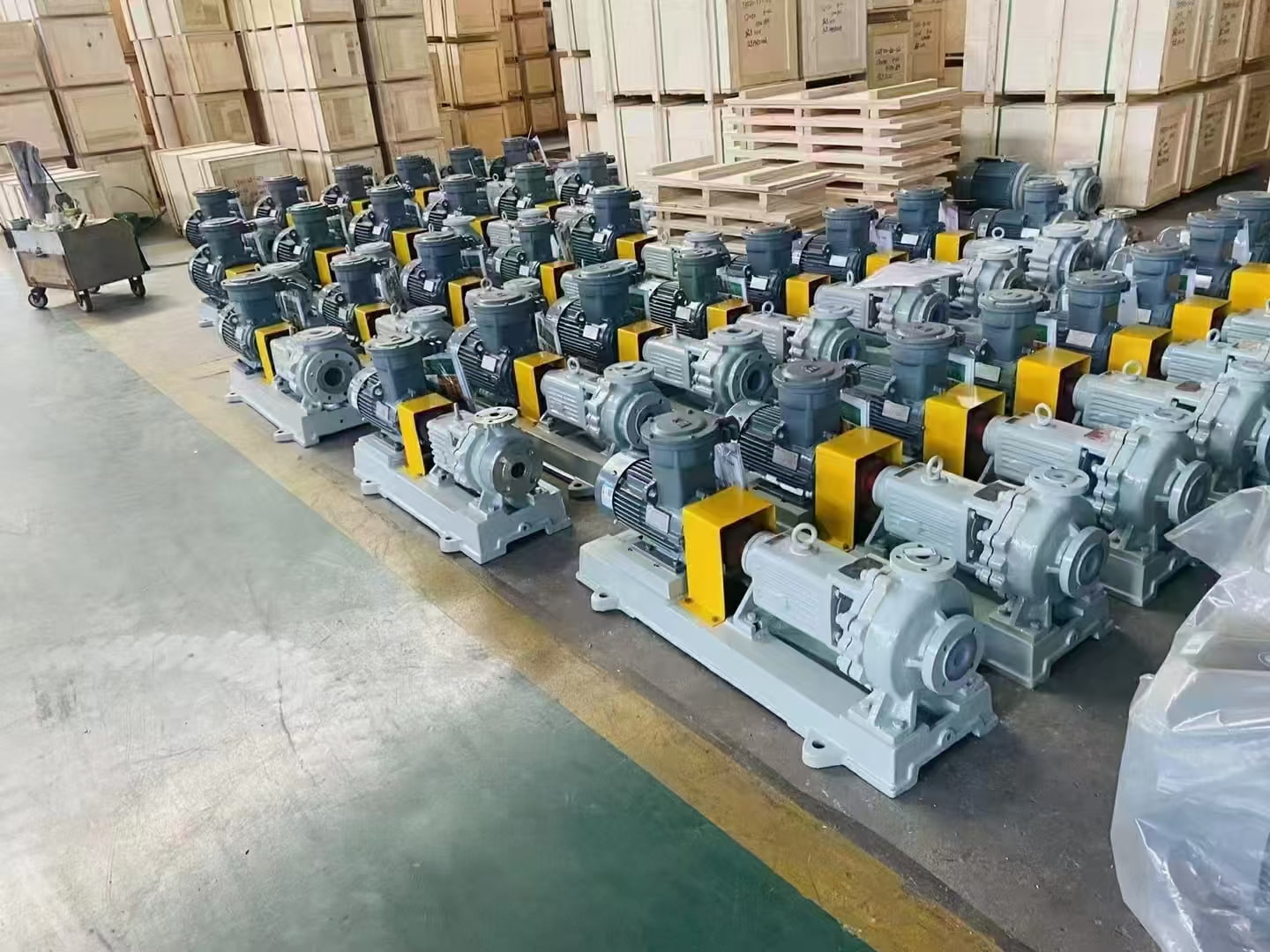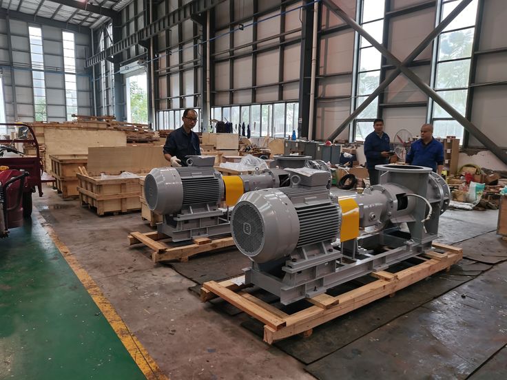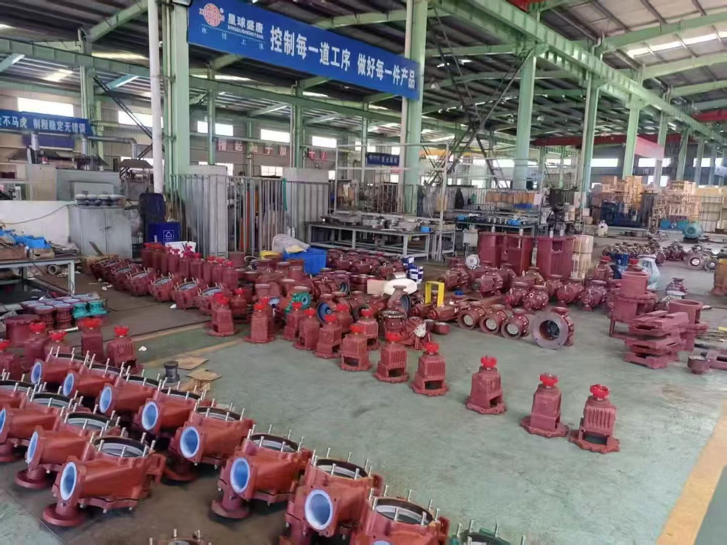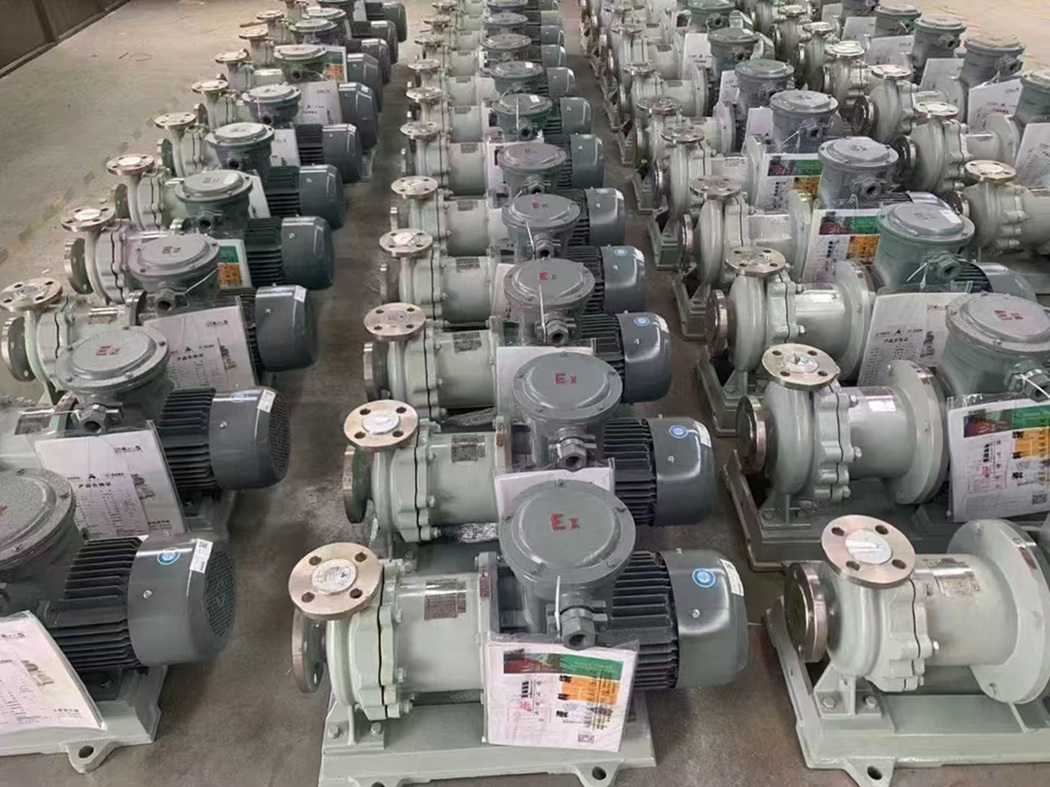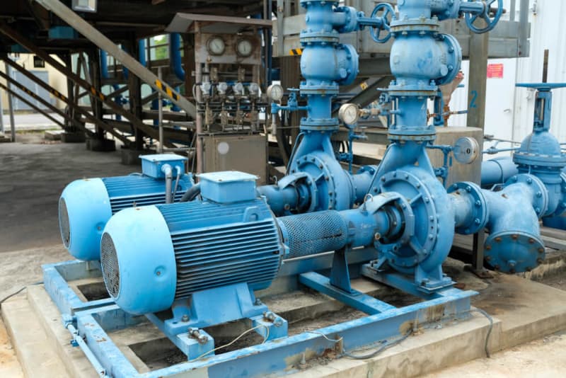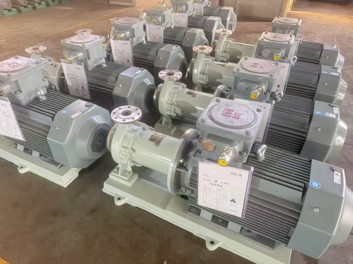
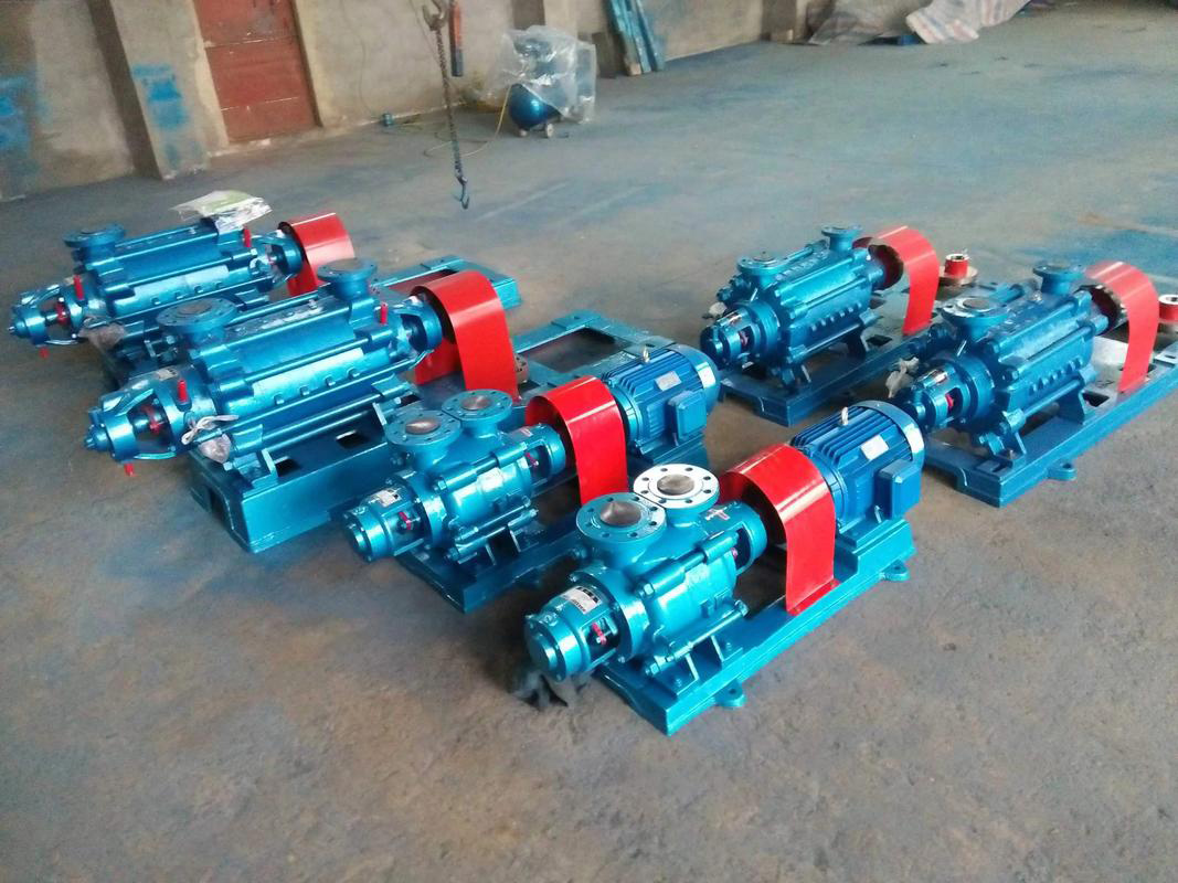
The horizontal multistage centrifugal pump is a type of fluid machinery primarily used for liquid transportation. It features high delivery efficiency and can be applied to the transfer of crude oil and chemical products, intermediate process liquids, cooling and circulation systems, as well as waste treatment and discharge. A petrochemical plant typically operates thousands of horizontal multistage centrifugal pumps. Prolonged operation inevitably leads to wear and technical failures, which can reduce operating efficiency and increase both production costs and the risk of shutdowns for maintenance. Currently, the petroleum industry generally adopts the DG-2499Y horizontal multistage centrifugal pump. Anhui Shengshi Datang will conduct an in-depth analysis of its technical parameters, explore possible causes of technical failure, and propose targeted maintenance recommendations to provide a systematic repair plan, ensuring equipment stability and continuous plant operation.
Technical Parameters
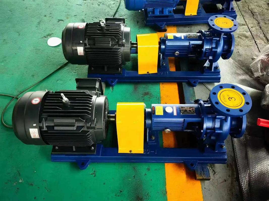
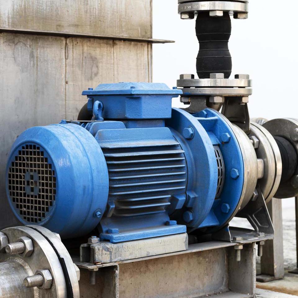
The horizontal multistage centrifugal pump consists of multiple pump stages connected in series, with each stage including an impeller and a corresponding diffuser. In each stage, the liquid gains kinetic energy through the impeller, which is then partially converted into pressure energy in the diffuser—thus progressively increasing the total output pressure of the pump.
This pump features a compact structure, ease of maintenance, and high efficiency in handling large flow rates, meeting high head requirements. Its rated flow ranges from 6 to 1000 m³/h, with a rated head between 40 and 2000 m. Operating speeds include 3500 r/min, 2900 r/min, 1750 r/min, and 1450 r/min, with a working frequency of 50 Hz or 60 Hz.
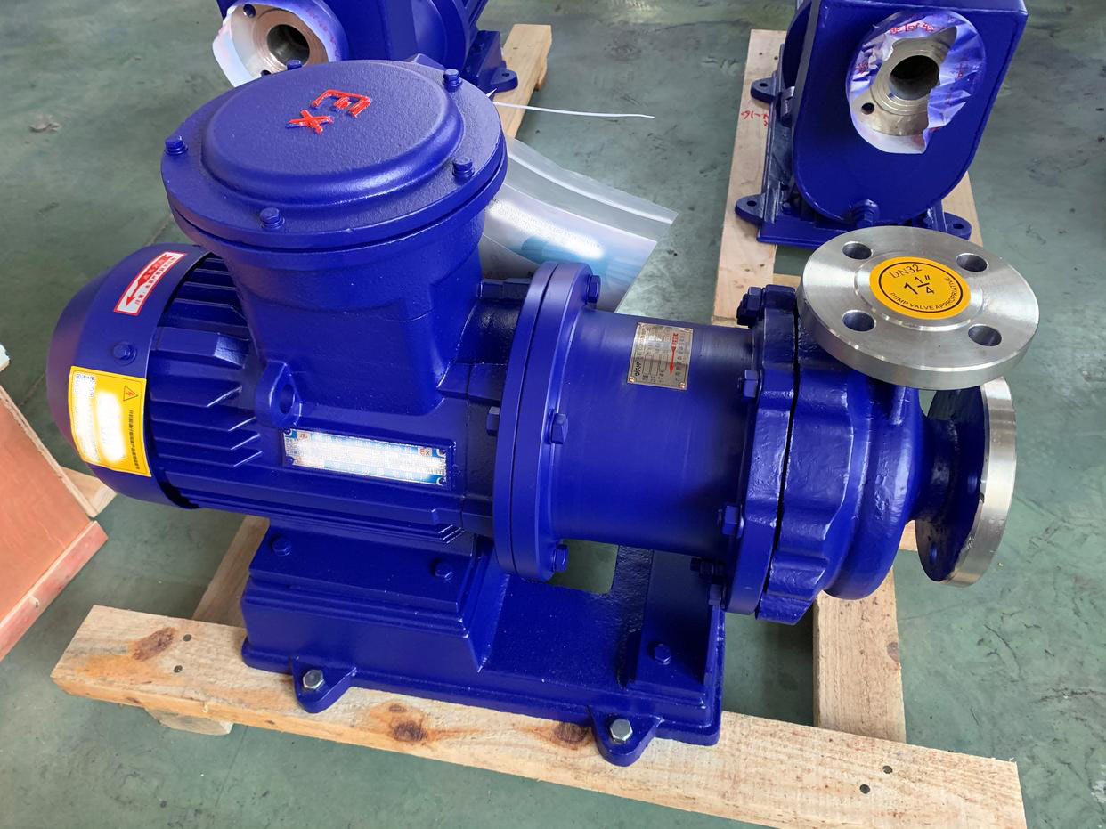
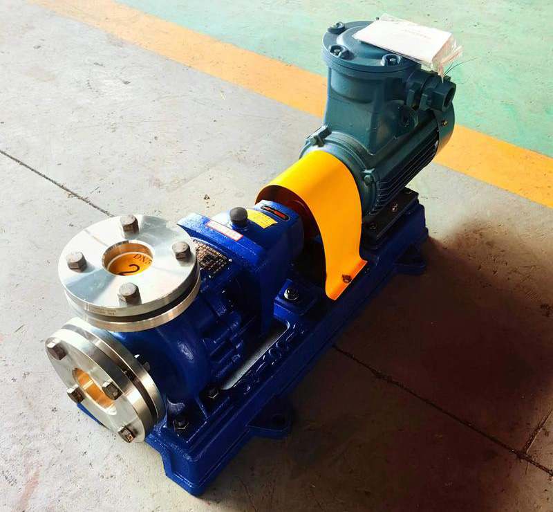
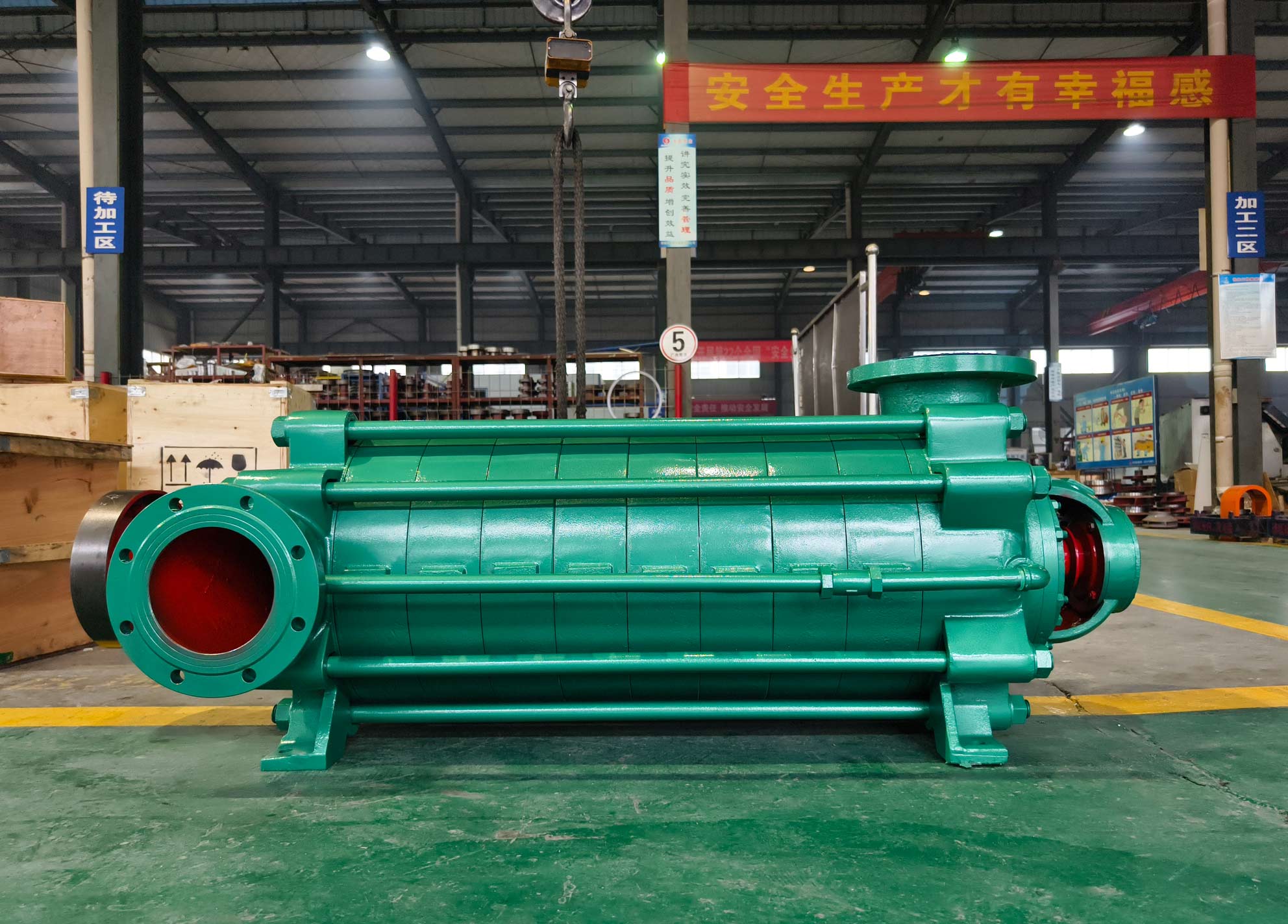
Taking the DG-2499Y horizontal multistage centrifugal pump as an example, its key technical features include:
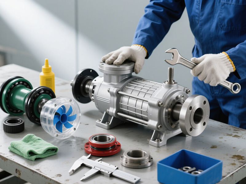
a. Two bearings installed on the front and rear shafts.
b. The pump and motor are connected by an elastic pin coupling, with the motor rotating clockwise during operation.
c. The suction inlet is set horizontally, while the discharge outlet is vertical.
d. Bearings are lubricated with grease, and the shaft seal can be either a packing seal or a mechanical seal.
Failure Cause Analysis
A. Dry Running Without Lubrication
Dry running occurs when the pump operates without sufficient lubrication due to failure or absence of lubricant. For the DG-2499Y pump, the bearings and shaft sleeves rely on lubrication to minimize friction and wear. Without lubrication, these parts can quickly wear out due to high friction and heat. The packing seal’s effectiveness may also decrease, leading to shaft seal failure and leakage. Excessive bearing wear can cause instability, resulting in impeller imbalance, increased vibration and noise, and reduced efficiency and lifespan. In extreme cases, complete bearing failure may occur, causing severe mechanical damage and shutdown.
B. Chemical Corrosion
In petrochemical applications, the DG-2499Y pump often handles chemically aggressive media such as crude oil, intermediate refinery products, and other chemical process fluids. These media may contain corrosive compounds such as sulfides, acids, and alkalis, which can attack metal components like impellers, shafts, and sleeves. Prolonged exposure leads to structural weakening, cracking, or pitting corrosion. Factors such as temperature, concentration, and flow velocity significantly affect corrosion rate. For instance, high temperatures accelerate corrosion, while high velocities can cause erosion–corrosion, where chemical attack and mechanical wear act simultaneously. Chemical reactions may also deteriorate packing and seal materials, reducing sealing performance and causing leakage or pump failure.
C. Overheating During Operation
During long-term operation, friction, poor heat dissipation, or high process fluid temperature may lead to overheating. Bearing overheating is common, often caused by insufficient or poor-quality lubricant. Under high-speed rotation, frictional heat between shaft sleeves can degrade material properties. Impellers and sealing rings may lose mechanical strength at elevated temperatures, reducing pump efficiency or causing structural damage. Insufficient flow in the recirculation or discharge lines can also lead to overheating, resulting in component fatigue, accelerated wear, and reduced service life.
D. Solid Particle Contamination
In petrochemical operations, pumps may be damaged by solid impurities in the conveyed medium—such as unreacted catalyst particles, sediments, corrosion products, or small debris. When these enter the pump, especially through the suction section and impeller, they increase wear on these components and reduce efficiency. Continuous particle erosion can severely wear sealing rings, shafts, and sleeves, leading to seal failure and performance degradation.
E. Cavitation
Cavitation occurs when the pressure at the suction side drops to or below the liquid’s vapor pressure, forming vapor bubbles that collapse in high-pressure regions. The resulting shock waves damage impellers and internal components. This phenomenon is common in petrochemical applications where volatile solvents or gases are present, especially under high-temperature or low-pressure conditions.
Key Maintenance Techniques
A. Zero-Flow Issue After Startup
a. When a DG-2499Y pump exhibits zero flow after startup, technicians should perform precise diagnostics:
b. Use pressure testing instruments to verify system sealing, ensuring no gas or liquid leakage, especially at the shaft seal and packing areas.
c. Monitor flow and pressure readings to identify internal blockages or piping faults.
d. Check motor-pump alignment to ensure efficient power transmission through the coupling.
e. Use infrared thermography to detect heat concentration indicating friction hotspots.
f. Replace or repair faulty components (e.g., impellers, bearings) and realign using laser tools.
g. Ensure all maintenance steps meet petrochemical safety and technical standards for stable operation.
B. Flow Rate Troubleshooting
a. Flow issues often result from chemical corrosion, solid contamination, or cavitation. Maintenance should include:
b. Evaluating the pump’s Q–H (flow–head) curve to determine deviations.
c. Cleaning or replacing worn or fouled impellers.
d. Inspecting and replacing worn sealing rings and bearings.
e. Measuring actual vs. theoretical flow using flowmeters and adjusting inlet valves as needed.
f. Checking for cavitation and optimizing NPSH (Net Positive Suction Head) conditions to prevent vapor ingestion.
g. Detecting blockages or leaks in the pipeline with ultrasonic flow and pressure sensors and repairing as required.
C. Overload in the Drive System
a. To resolve motor or drive overload:
b. Conduct full performance tests using instruments like clamp ammeters and power analyzers to ensure operation within rated limits.
c. Inspect impellers, bearings, and seals for wear or damage that may increase load.
d. Remove internal blockages and ensure smooth fluid flow.
e. Precisely align the pump and motor to reduce mechanical transmission losses.
D. Bearing Overheating
a. Maintenance steps include:
b. Using vibration analyzers to detect abnormal bearing vibration—an early sign of overheating.
c. Regularly monitoring bearing temperature via infrared thermography; disassemble and replace damaged bearings when necessary.
d. Inspecting and cleaning the lubrication and cooling systems to ensure proper lubricant flow and quality.
e. Verifying correct bearing installation and alignment to minimize frictional heat.
E. Vibration Troubleshooting
a. Pump vibration may result from impeller blockage or imbalance, misalignment, or loose components. Maintenance personnel should:
b. Use vibration and laser alignment tools to diagnose misalignment.
c. Adjust bearing preload to prevent overheating and vibration.
d. Inspect impellers for damage or imbalance and perform dynamic balancing if necessary.
e. Tighten all fasteners, including shaft sleeve nuts and bolts, to ensure structural stability and safe operation.
...