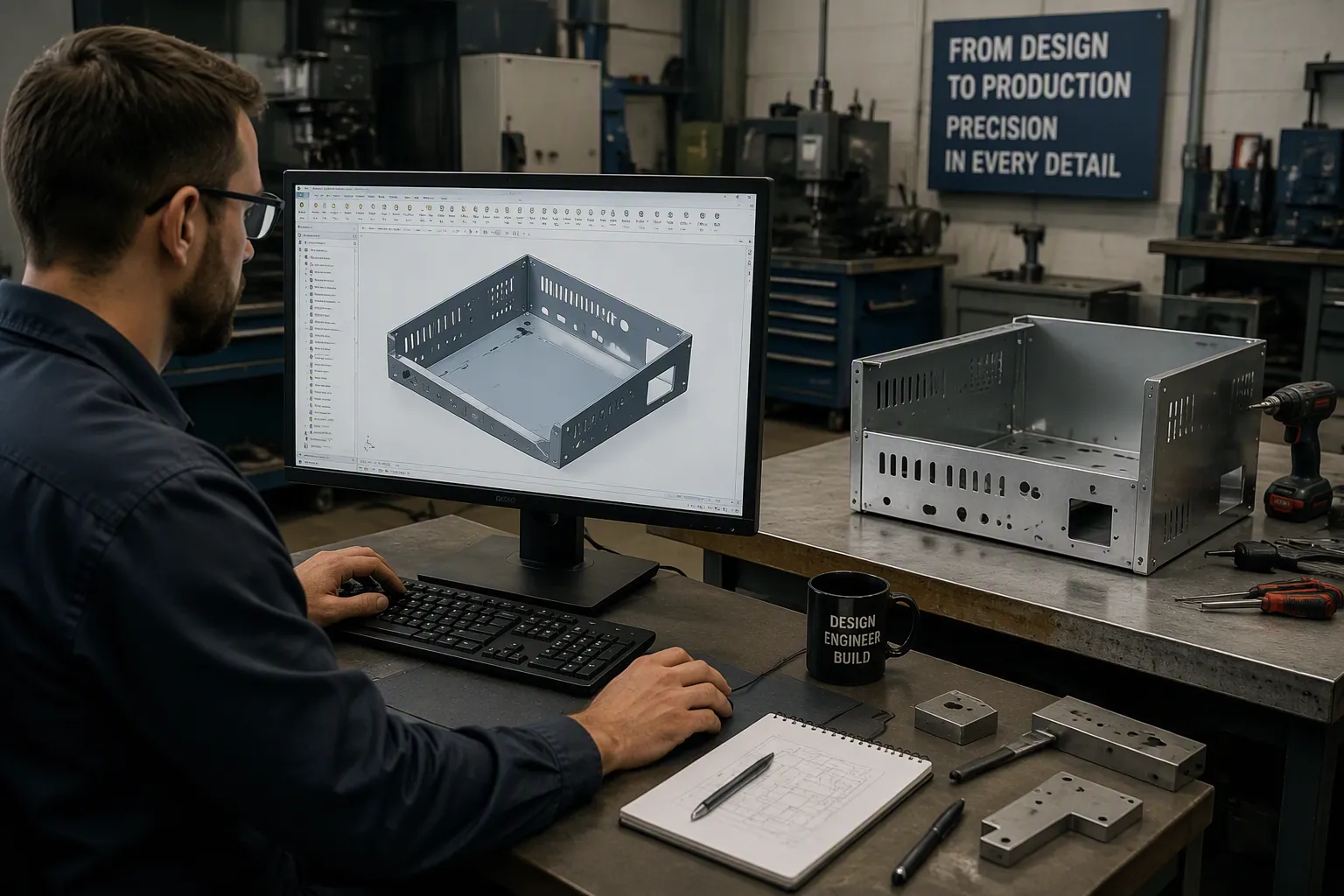
The sheet metal fabrication process transforms flat metal stock into precise, durable parts through cutting, forming, joining, and finishing steps. Your path from a CAD model to a finished assembly directly determines part accuracy, production cost, lead time, and overall quality. HPS manages this entire path in-house, giving you a single point of accountability from digital design through final assembly.
Key Takeaways
-
Early design feedback saves time and money by catching problems before production.
-
CAD models and simulations help you create accurate parts without wasting materials.
-
A single partner for design, fabrication, and assembly ensures quality and speeds up your project.
The Sheet Metal Fabrication Process: From CAD to Production-Ready Design
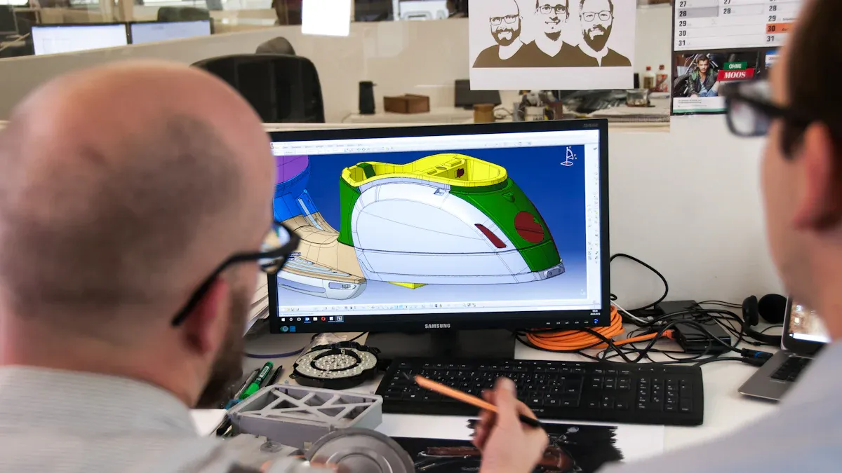
Building the 3D Model in CAD
You start the sheet metal fabrication process by building a precise 3D model in CAD software. Modern platforms offer automatic flat pattern creation, real-time bend allowances, and bend radius calculations. The K-factor defines the neutral axis location relative to material thickness. CAD software uses this value to compute bend allowance, which is the neutral axis length along the bend arc. Adding bend allowance to flange lengths yields the total flat length. Accurate K-factor values prevent material waste and ensure precise flat patterns.
Finite Element Analysis (FEA) and Design Validation
FEA simulates how your part performs under real-world loads. Parametric modeling supports top-down assembly design, where master models define geometric constraints that cascade through components. This approach enables rapid customization without compromising dimensional integrity. Early-stage error detection identifies manufacturing conflicts before production begins. Digital verification replaces traditional trial-and-error methods that consume time and materials.
Design for Manufacturability (DFM) Feedback
DFM feedback identifies manufacturing risks before production starts. Reducing scrap directly translates to lower material consumption, less machine time, and better margins. Real-time DFM feedback eliminates feedback latency, which ranks among the highest-impact hidden delays in prototyping. Responding promptly to supplier DFM feedback typically pays off in schedule time. Applying DFM early and validating digitally before cutting material reduces iteration count and minimizes material waste.
Material Selection and Thickness Decisions
Material selection balances cost, strength, weight, and corrosion resistance. Consider these common options:
|
Material |
Cost |
Strength |
Weight |
Corrosion Resistance |
|---|---|---|---|---|
|
6061-T6 Aluminum |
Cost-effective |
~40 ksi yield |
Low |
Good (when anodized) |
|
5052 Aluminum |
Moderate |
Moderate |
Low |
Superior formability |
|
304 Stainless Steel |
Moderate to high |
High |
Higher |
General corrosion |
|
316 Stainless Steel |
High |
High |
Higher |
Marine/chemical exposure |
Define application requirements clearly before selecting material. A material selection matrix compares candidates using weighted criteria. This structured approach helps you make transparent decisions.
Cutting, Bending, Welding, and Finishing the Metal
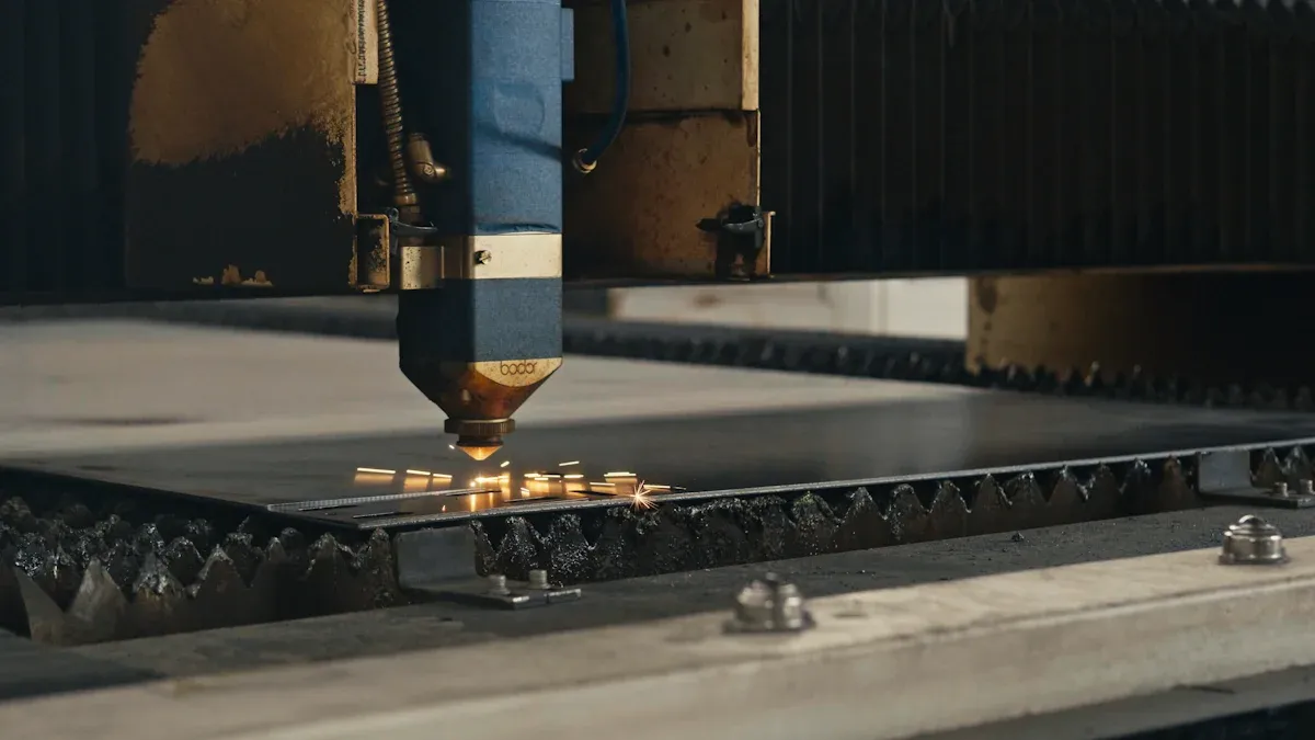
Once your design passes DFM review and material selection, the physical work begins. The sheet metal fabrication process now moves from digital models to shop floor operations. Cutting, bending, welding, and finishing each require specific equipment, skill, and quality checks. Understanding these steps helps you anticipate costs, lead times, and design limitations. HPS operates state-of-the-art fiber laser cutting systems, CNC press brakes, and robotic welding stations to execute each step with precision.
Laser Cutting and Punching
Modern fiber laser cutting delivers remarkable precision. Kerf width ranges from approximately 0.08 mm to 0.45 mm (0.003 in. to 0.018 in.), depending on material type, thickness, laser power, and focus settings. Part dimensional tolerances on Bystronic fiber lasers reach ±0.125 mm to ±0.25 mm (±0.005 in. to ±0.010 in.). These values shift with alloy, thickness, and part geometry.
Laser cutting and punching serve different niches in the sheet metal fabrication process. Lasers excel at complex and arbitrary contours, tight inside corners, fine detail, one-off and low-volume work, and reflective or thicker materials when using fiber lasers. The non-contact cut produces no part distortion from punch force. Punching shines for high-volume repeated hole patterns, standard round and shaped holes matching available tooling, and formed features the laser cannot produce — louvers, countersinks, extrusions, and dimples. Punching leaves a characteristic edge with a rollover and burnished band on the punch-entry side, plus a fracture zone with a burr on the die side.
Several factors drive your choice between turret punching and laser cutting:
|
Factor |
Turret Punching |
Laser Cutting |
|---|---|---|
|
Material Type and Thickness |
Best for thin sheets (0.5–3 mm) like mild and galvanized steel; less effective on thicker materials |
Effective on a wide range of materials up to ~10 mm, including reflective metals (with fiber lasers), and non-metals; better for thicker materials |
|
Part Complexity |
Challenging for intricate details; relies on available tool shapes |
Easily cuts complex, detailed geometries with high precision |
|
Production Volume |
More efficient and cost-effective for high-volume, simple, repetitive patterns |
Faster for low-to-medium volumes, especially for detailed or diverse parts |
|
Customization and Tooling Costs |
Requires specific tools per pattern, increasing tooling costs for one-off designs |
No tooling costs; offers greater design flexibility and easy modifications |
|
Edge Quality and Secondary Processing |
May need deburring or smoothing depending on material and tool |
Typically produces cleaner edges, reducing or eliminating finishing work |
|
Cost-Effectiveness |
Lower machine cost; operational cost ~$20–$50/hour; economical for bulk simple production |
Higher initial and operating cost (~$50–$120/hour); more efficient for complex designs and material conservation |
The practical split is clear: lasers handle geometry and detail while punching handles volume hole patterns and formed-in features.
Press Brake Bending and Forming
CNC press brakes transform flat cut blanks into three-dimensional parts. Modern digital control systems easily guarantee a bending angle tolerance of 1 degree, with measurement precision reaching 0.01 degrees. Material springback presents the primary challenge. For standard radius bending, springback ranges from 20 to 30 percent depending on material. Coining — which requires six times more force than air bending — eliminates springback entirely.
Press brake tolerance depends on material type, machine tool accuracy, and project requirements. Carbon steel can achieve a tolerance of ±0.010 inch. Stainless steel requires looser parameters due to its springback characteristics. Material properties such as hardness, ductility, and yield strength directly affect how sheet metal bends under pressure. Harder materials like stainless steel and carbon steel tend to spring back after forming, requiring careful adjustment of bend angle and force to maintain accuracy. HPS press brake operators use advanced angle measurement feedback to compensate for material variation in real time.
Welding Techniques and Joint Design
Welding joins individual sheet metal parts into assemblies. Joint design directly controls distortion, strength, and manufacturability. Design guidelines help you minimize heat distortion and maximize joint strength:
-
Add stiffness through joint geometry. Flanges, hems, and formed edges stiffen thin sheet metal and resist distortion better than welding along free edges.
-
Break long seams into shorter welds. Intermittent welds reduce sustained heat input and let the part cool between passes, cutting panel bowing.
-
Balance welds across the part. Symmetrical weld placement distributes thermal contraction evenly and prevents one-directional pulling.
-
Design for welding sequence. Grouping welds symmetrically and avoiding long one-sided passes supports better sequencing.
-
Accept small geometry changes for stability. Wider flanges, small ribs, or modified panel geometry increase stiffness with minimal functional impact.
-
Manage the heat-affected zone (HAZ). Avoid placing highly stressed or cosmetic-critical features next to welds. Add local stiffness or specify post-weld finishing where unavoidable.
-
Ensure weld accessibility and tool clearance. Provide clearance for TIG torches, MIG guns, and spot-welding electrodes. Redesign joints by adding flanges, changing overlap direction, or repositioning welds rather than forcing difficult welds.
-
Balance joint strength against heat input. Review weld size and length against structural requirements to avoid over-welding thin sheet.
-
Consider alternative joining methods. Rivets, clinching, and structural adhesives introduce little to no heat. They are preferable where distortion control is the priority. Hybrid strategies like spot welds plus adhesive can improve both performance and manufacturability.
Different joint types behave differently under welding:
|
Joint Type |
Distortion Behavior |
Strength / Use Notes |
Design Implication |
|---|---|---|---|
|
Lap |
Double thickness traps heat; distortion rises with continuous welds |
Good shear strength; forgiving of fit-up |
Use spot or intermittent seam welding |
|
Butt |
Sensitive to fit-up; gaps raise heat input and distortion |
Flush cosmetic finish |
Add backing or flanges for weldability |
|
Corner |
Heat concentrated along a low-stiffness edge |
Structurally efficient for enclosures/frames |
Add small flanges or use intermittent welds |
|
Flanged |
Lower distortion than welding a free edge |
Stable welding surface, repeatable |
Preferred for dimensional stability in thin sheet |
Practical design principles guide your welding approach:
-
Use outside corner welds for superior penetration, better fill, and fuller appearance. T-joint welds offer excellent shear strength for stiffeners, gussets, and baffles. Inside corner and inside fillet variants suit cases where weld protrusions are not permitted.
-
Design for bending first. Welding is a secondary process after bending. Complete 3D bend modeling first and check bending-tool clearance so welding flanges do not obstruct the bending stroke.
-
Never draw fillet welds, beads, or weld cutouts in CAD. The model must reflect true un-welded bend geometry, with weld compensation calculated by CAM.
-
Account for non-sealing welds. Laser welding provides structural connection and alignment, not watertight or gastight seals. Bend relief gaps and open seams are not auto-filled. Specify sealant or manual full-fill grinding if sealing is required.
-
Use tab-and-slot self-alignment. Interlocking tabs and slots cut during laser cutting give precise alignment without fixtures, eliminating cumulative assembly error. Tab width should be 3 to 5 times sheet thickness with 0.1 to 0.15 mm unilateral clearance.
-
Add laser-cut locating holes (3.0 to 5.0 mm) on non-welded datum surfaces for dowel pins, spring pins, or locating bolts. These improve high-volume assembly consistency and provide an inspection datum.
Surface Finishing and Coating Options
Surface finishing protects your parts from corrosion and provides the desired appearance. Different finishes offer different levels of corrosion resistance at different costs:
|
Finish Type |
Salt Spray Hours (ASTM B117) |
Cost Range (per sq ft) |
|---|---|---|
|
Powder Coating |
500–1,000+ (super-durable resins can exceed 2,000) |
$0.75–$2.50 |
|
Zinc Plating |
200–500 |
$0.30–$1.00 |
|
Anodizing (Type II) |
1,000+ |
$0.80–$2.00 |
|
Anodizing (Type III hard coat) |
2,000+ |
$1.50–$4.00 |
|
Zinc-Nickel Plating |
800–1,200 |
$1.50–$3.50 |
|
Electroless Nickel Plating |
500–1,000+ |
$2.00–$5.00 |
|
Chrome Plating (decorative/hard) |
Not specified |
$3.00–$10.00+ |
Each finish serves specific applications:
-
Powder coating offers the lowest cost tier. It works best for outdoor parts, color variety, and large components. The limitation: it is not electrically conductive.
-
Zinc plating falls in the mid-low cost range. It works best for budget corrosion protection and fasteners. The limitation: limited color options.
-
Anodizing sits in the mid cost range. It works best for aluminum hardness and wear resistance. The limitation: aluminum only, fewer colors.
-
Zinc-nickel plating represents the highest cost tier. It works best for harsh environments and automotive applications. The limitation: higher cost, complex process.
-
Electroless nickel plating falls in the mid-high cost range. It works best for uniform coating on complex shapes. The limitation: lower conductivity.
Your choice depends on the operating environment, budget, and functional requirements. HPS guides you through finish selection to match performance needs with cost constraints.
Inspection, Tolerances, and Final Assembly
First Article Inspection and In-Process Checks
First Article Inspection validates your first production part against all design requirements. The Sheet Metal Fabrication Process includes First Article Inspection as a critical quality gate. You follow the AS9102 standard to structure this validation. You balloon engineering drawings and create an inspection plan. Form 1 tracks part number accountability. Form 2 documents material and process accountability. After manufacturing the part, you measure every critical feature with calibrated tools. Functional testing verifies assembly fits. You compile results into AS9102 Form 3. In-process checks occur at each production stage. Operators verify bend angles, hole positions, and surface conditions continuously. This approach catches deviations before they compound into costly rework.
Managing Tolerances and Common Fabrication Challenges
Common tolerance deviations in sheet metal include:
-
Hole position accuracy depends on laser cutting capability and material thickness
-
Flange length deviation occurs from material springback during bending
-
Bend angle challenges arise with high-springback materials such as stainless steel
-
Flatness deviation affects large thin panels after welding or forming
-
Slot width variation impacts assembly fit for mating components
Material selection significantly influences achievable tolerances. Short flanges require complex manufacturing because they lack proper press brake support. Tolerance stacking across multiple bends makes final dimensions difficult to hold, especially in thin flexible materials.
When to Relax Tolerances for Cost and Speed
Relaxing tolerances where high precision is unnecessary can lead to significant cost savings without compromising functionality. Changing a tolerance from ±0.05 mm to ±0.5 mm on non-critical dimensions simplifies production processes and reduces scrap rates.
You start this process by identifying the crucial assembly stack-up. Gather dimensional inputs from drawings and CAD models. Choose your analysis method between worst-case or statistical analysis. Build the tolerance chain linking all key features. Optimize the design by loosening non-crucial tolerances first. This tiered approach focuses manufacturing resources only where function requires precision.
Assembly, Integration, and Functional Testing
Assembly methods for sheet metal components vary in strength, speed, and cost:
|
Method |
Best For |
Strength |
Relative Cost |
|---|---|---|---|
|
Spot Welding |
High-volume thin gauge |
High |
Low |
|
MIG/TIG Welding |
Structural weldments |
Very High |
Medium |
|
Riveting |
Permanent no-heat joints |
Medium |
Low–Medium |
|
Clinching |
Lightweight no-hardware joints |
Medium |
Low |
|
Adhesive Bonding |
Mixed materials cosmetic surfaces |
Medium |
Medium |
Finish thickness affects assembly fit. Coatings change hole sizes and slot dimensions. A design that assembles perfectly in raw metal may cause interference after coating. Functional testing validates complete assembly operation per specifications. You verify fit and performance under expected conditions. HPS manages this entire process under one roof, ensuring quality through every stage.
The sheet metal fabrication process is a connected sequence. CAD design defines the part, fabrication shapes it, and inspection and assembly verify it. Early DFM collaboration, controlled tolerances, and disciplined quality checks prevent costly rework and delays. HPS delivers end-to-end fabrication—design support, precision cutting and forming, welding, finishing, and assembly—under one roof, shortening lead times and reducing handoff errors. Contact HPS to turn your CAD files into reliable, production-ready assemblies.
FAQ
What tolerances can sheet metal fabrication achieve?
You can expect ±0.125 mm to ±0.25 mm on laser-cut parts. Press brake bending typically holds ±1 degree. HPS matches tolerances to your functional requirements.
How long does sheet metal fabrication take?
Lead time depends on complexity, volume, and finishing. Prototypes ship in days. Production runs take weeks. HPS provides timelines during your DFM review.
Can HPS handle both prototyping and production?
Yes. HPS supports you from single prototypes through high-volume production. You get consistent quality and one point of contact across every stage.